1TG – Design & Build of the One Tonne Guerilla

Archive for the 'Design' category

Written by Doug | Posted in Design | No Comments »

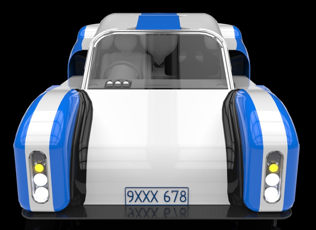
a design aspect I’ve been working on a bit lately is the bodywork.

This is  proving troublesome as I am not in the least bit artistic and my chosen tool to date is not a ‘real’ surfacing program.  Essentially I’m not happy with most of the work done to date.  If you take a look at the picture below for example to me its pretty average…

Nose

More work definately required there, but then if you look at this…

It doesn’t look that great either, but of course in real life it looks like this…

Bentley.

Which is pretty darn good looking if you ask me.  So how to separate a design that IS rubbish from one that looks rubbish in CAD is clearly a problem I will need to sort out at some point.

Written by Doug | Posted in Design | No Comments »

It’s Monday night and whilst I should be in the garage working on the car I really can’t be bothered with that tonight so I thought I’d add a little to the site.

I’d recently started this build thread on GT40s.com as a way for people to comment on the thing and to share the experience of its construction. One of the questions I been asked (not for the first time) is “Why does it have so much cross bracing in it”.

Well to understand that I need to explain how I designed the thing in the first place. So I’ll go back to the beginning.

Some fundamental stuff.

Things are the shape they are for two reasons:

1. The material they are made of.

2. The tools at the manufactures disposal to form that material into a different shape.

If you think about it, fundamentally virtually every advancement in Engineering for the last 100 years or so has been made possible because of a previous advancement in a material or manufacturing process, which is off of the subject.

This means for the backyard car builder you have to choose a material that you can effectively form into the required structures with the tools at your disposal and work with that material to achieve the required objective, this will inevitably lead the final creation to have certain basic characteristics because of the material choice.

This choice for me was to use SHS25mm x 1.5mm 350MPa Steel tube as the basis of the design, I made this choice as:

1. The material is easily worked with.

2. Joining methods are well known, understood and readily done in the shed.

3. Readily available

4. Cheap.

Equally importantly I feel in selecting the material you are going to work with is whether you actually understand its properties properly or not. For Steel I felt I did whereas for other materials I could have decided to make the frame of the car from I felt like it did not.

Steel.

Steel is marvellous stuff. One of its more or less unique properties is that if not stressed beyond a certain point (which is calcuable) it will not fatigue, which is great for something like a car that’s constantly being bounced and vibrated from many sources.

Strength.

Steel is often quoted as having a particular Tensile strength which is great but you can’t design to use all of that strength on a regular basis as it’s beyond the Yield point of the material, the yield point is the point beyond which if you stretch it the material will not return to its original length. Steel framed buildings are typically loaded to just 10% of their tensile strength in normal operation for example.

Strain.

If you load a material it will stretch, divide the original length of a loaded member into the amount it has changed in length, that is the strain.

The simplistic and obvious point here is that when stretching a member the amount of strain is proportional to the length of the member, if you take a rubber band cut it and hang a weight from it the amount it stretch’s will be proportional to the length of the rubber band i.e. halve the length of the rubber band and the amount it will stretch will be halve also.

For members in tension the point here should be obvious the shorter the member the less strain in it for a given load, therefore by keeping members as short as possible between support locations the amount of strain in the member can be kept to a minimum, obviously the strain in the whole structure still adds up but at a support point there is the opportunity to divide the load amongst other members and thereby reduce the strain again.

Euler.

This is all very good for members in tension but for those in compression things are more complex firstly the shape of the member (its second moment of area) as well as the strength of the material have an effect on how large a load you can put on a member before it collapses. Leonhard Paul Euler worked this all out and was genius enough to come up with the math behind it too. The salient point to the math is that it’s a square rule i.e. as columns get longer they get exponentially weaker in compression and vice-versa again the shorter the length the column becomes exponentially stronger in compression.

Stiffness

So armed with information we’ll try and design a structure that’s as stiff as possible, sufficiently strong and no heavier than it needs to be. And here come the counter intuitive part (for me at least). When trying to make a structure stiff the aim is to make the load attempt to induce as much strain as possible in the structures members. This means not only, not loading a member in bending but also arranging a member to act as directly as possible against the direction from which the load is coming.

Ok that’s enough for one night look up on Wikipedia things I’ve not explained, and if there’s a positive response to this I might and some more another night that the shed just isn’t appealing.