June 1, 2010
Recently I’ve been trying to figure out how to measure bump steer, there’s a number of methods I’ve found on the web using a laser level, the issue is though that any point on the outside of the wheel describes an arc when the suspension is moved through its range.
This arc needs to be cancelled out before the underlying bump steer can be revealed.
Then I had an idea, which I doubt is original but seemed a neat way to get around the issue and still give accurate measurement without a high precision set up being required.
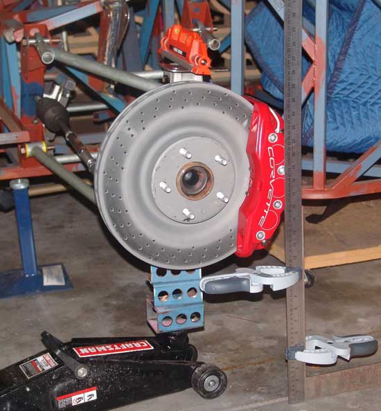
So what I did was set a laser level on top of the suspension upright at basically 90 degrees to the rotation of the wheel, hence when the suspension is moved up and down the laser should describe a straight line on the surface it falls on, in this case it was a piece of cardboard some 3.4m away, the further the distance the greater the amplification on any bump steer present. The vertical movement on the cardboard is not important neither is getting the laser level as its only the left – right movement that’s of interest.
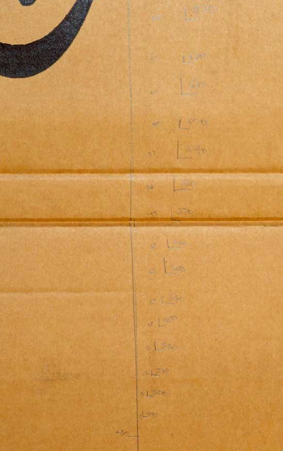
So a vertical line was drawn on the card board the laser lined up on it and measurements taken at 10mm intervals from full drop to beyond full bump.
Below shows the set up, the laser doesn’t need to be fixed very well in position providing you don’t touch it during the operation.
Here’s the numbers on the wall…
Which with a bit of math turns into:
| From Ride Height | Wheel Height | Wall Offset | Offset | Angle | Distance at Rim | |
| 85 | 630 | 45 | 20 | 0.32 | 1.29 | |
| 75 | 620 | 42 | 17 | 0.27 | 1.10 | |
| 65 | 610 | 40 | 15 | 0.24 | 0.97 | |
| 55 | 600 | 40 | 15 | 0.24 | 0.97 | |
| 45 | 590 | 37 | 12 | 0.19 | 0.78 | |
| 35 | 580 | 34 | 9 | 0.14 | 0.58 | |
| 25 | 570 | 33 | 8 | 0.13 | 0.52 | |
| 15 | 560 | 30 | 5 | 0.08 | 0.32 | |
| 5 | 550 | 27 | 2 | 0.03 | 0.13 | |
| Ride Height => | 0 | 545 | 25 | 0 | 0.00 | 0.00 |
| -5 | 540 | 23 | -2 | -0.03 | -0.13 | |
| -15 | 530 | 20 | -5 | -0.08 | -0.32 | |
| -25 | 520 | 16 | -9 | -0.14 | -0.58 | |
| -35 | 510 | 12 | -13 | -0.21 | -0.84 | |
| -45 | 500 | 8 | -17 | -0.27 | -1.10 | |
| -55 | 490 | 5 | -20 | -0.32 | -1.29 | |
| -65 | 480 | 0 | -25 | -0.39 | -1.62 |
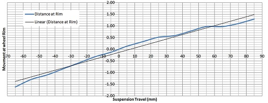
Or looks like this as a graph…
The most common opinion I can find is that zero bump steer in the ideal, what is a practical target though is not very often mentioned the closest I’ve found is this:
“For reference, current Porsche 997 GT3 cannot obtain zero bump steer. In order to do so, the rack would have to be relocated and it’s simply not possible given the packaging of the front tub section. The baseline set-up these cars use for almost all tracks seems to be 0.5 mm static toe out per side in front and 2.5-3 mm static toe in per side at the rear. Front bump steer can add typically as much as 1.5 mm per side under full bump while the rear adds roughly 0.5 mm.”
Which comes from here which leads me to think what I’ve got is not bad and I’ll wait until the final car set up before trying to tweak it to be any better than current. What I don’t like about the current set up is that it generates roll toe-in, but is the movement enough to worry about? I’m not sure at this stage, neither do I know what direction to move the rack in to fix the issue, I suspect its forward though.
| From Ride Height | Wheel Height | Wall Offset | Offset | Angle | Distance at Rim | |
| 85 | 630 | 45 | 20 | 0.32 | 1.29 | |
| 75 | 620 | 42 | 17 | 0.27 | 1.10 | |
| 65 | 610 | 40 | 15 | 0.24 | 0.97 | |
| 55 | 600 | 40 | 15 | 0.24 | 0.97 | |
| 45 | 590 | 37 | 12 | 0.19 | 0.78 | |
| 35 | 580 | 34 | 9 | 0.14 | 0.58 | |
| 25 | 570 | 33 | 8 | 0.13 | 0.52 | |
| 15 | 560 | 30 | 5 | 0.08 | 0.32 | |
| 5 | 550 | 27 | 2 | 0.03 | 0.13 | |
| Ride Height => | 0 | 545 | 25 | 0 | 0.00 | 0.00 |
| -5 | 540 | 23 | -2 | -0.03 | -0.13 | |
| -15 | 530 | 20 | -5 | -0.08 | -0.32 | |
| -25 | 520 | 16 | -9 | -0.14 | -0.58 | |
| -35 | 510 | 12 | -13 | -0.21 | -0.84 | |
| -45 | 500 | 8 | -17 | -0.27 | -1.10 | |
| -55 | 490 | 5 | -20 | -0.32 | -1.29 | |
| -65 | 480 | 0 | -25 | -0.39 | -1.62 |


1 thought on “June 1, 2010”
Comments are closed.